
Introduction
As the world transitions to renewable sources of energy to fight the effects of climate change it is important to develop strategies and technologies that will allow these sources of energy to meet demand. Electrical energy storage is a key part of the push to integrate more renewable energy sources into electricity generation around the world. In order to store even 20% of the electricity generated from solar and wind systems approximately 700 gigawatt-hours (GWh) of energy storage is needed [1]. The United States had an electrical storage capacity of 431 MWh in 2017 compared to 4 billion megawatt-hours (MWh) of electricity generated that same year [2]. This energy storage is essential for intermittent generation sources like wind and solar to be able to provide power when the sun isn’t shining, or the wind isn’t blowing.
Energy storage systems have two criteria that are especially important to consider: energy density and efficiency of the system. Energy density is a measure of how much energy can be stored per unit of volume while the efficiency is what percentage of energy can be stored and later extracted for future use [4]. These metrics govern how feasible an energy storage option may be. The smaller the energy density the more space a system must take up to meet demand; the less energy efficient a storage option is the more energy it throws away. In order to be sustainable and economical, energy storage solutions must prioritize these options so that they can be competitive with current fossil fuel energy production methods to encourage the use of renewable energy sources.
Energy Storage Options
There are a number of methods for storing the electrical energy needed to make renewables a more viable solution. Some of these technologies are widespread and have been in use for decades while some are leveraging new technologies to store this energy more compactly and more efficiently.
Pumped Hydro
The most common method for storing electrical energy in the United States is pumped hydro. This technology involves pumping water uphill to a reservoir usually during periods of low demand so that it can flow downhill later to spin a turbine when energy is needed. This type of energy storage accounts for 94% of all US electrical energy storage for a total of approximately 23 GW [3]. These systems typically have a roundtrip efficiency of 70-85% with an energy density of 0.2-2 watt-hour per liter (Wh/L) [2]. The main disadvantage of a pumped hydro system is that it is extremely dependent on the region it is located in for sufficient elevation changes.
Compressed Air
Another energy storage method largely reliant on location and natural features is large scale compressed air energy storage (CAES). This technology also typically leverages using off peak power to compress air so that it can later be used to spin a turbine to produce electrical energy. Air is typically compressed between 40-70 bar at ambient temperatures and is stored in natural features like salt caverns which use geostatic pressure to help contain the air [4]. There are two CAES facilities currently in use, one near Berlin, Germany, and another in MacIntosh, Alabama. The Alabama facility is capable of 100 MW of power for 226 hours and 2,555,000 m3cavern to store the air [4].
Compressed air is not very popular because it is so geographically dependent, but also because the efficiencies of the system vary wildly. Traditional CAES systems have an efficiency of 40-50% because the air is heated before expansion by fossil fuels [5]. However, there are ways to improve that efficiency; if thermal energy storage is used to trap heat that escapes during the compression stage it can be reused to heat the air before expansion, raising efficiencies above 90% [5]. Regardless, CAES systems have a relatively low energy density of between 2 and 6 Wh/L [2]. Both pumped hydro and CAES have a future in the field of energy storage but are not good widespread solutions due to the low energy density and geographical restraints of both.
Lithium Ion
Lithium-ion (Li-ion) battery technology was first introduced in the 1990’s for storing energy to power electronics, but recently has become more common for powering cars along with laptops and phones, and it is even used for large scale energy storage. Li-ion batteries have tremendous energy density of 200-400 Wh/L and efficiencies ranging from 85-95% [2]. However, they can only sustain for 1,000-10,000 cycles [2] which does not make them an ideal candidate for large-scale sustainable grid storage. As the Li-ion batteries reach the end of their cycle life, the heavy metals in them like lithium and cobalt that give them their energy density wear out and need to be replaced. This results in more mining of rare and precious metals which can cause significant environmental damage as well as reducing resources. Due to the high energy density, Li-ion should be prioritized for electronics that need to be portable like cellphones, laptops, and cars, and using it for grid storage has the potential to put undue stress on the global supply chain for the metals that make these batteries possible.
Flow Batteries
Flow batteries are another option for grid-scale energy storage. They operate as an electrochemical conversion device, with two oppositely charged electrolyte solutions that flow over opposite sides of a membrane that allows for the exchange of electrons and ions. The electrolytes undergo a redox reaction that results in energy being stored in the fluid which can later be used to provide electrical energy [1]. Flow batteries have efficiencies ranging from 60-85% with an energy density of 20-70 Wh/L and a cycle life of 12,000-14,0000 cycles [2]. Traditionally, redox flow batteries use vanadium in the electrolyte which poses issues because vanadium is a scarce metal that can be hard to come by and poses environmental risks due to the toxicity of mining the metal. Research has been conducted into replacing the vanadium in these systems with iron, which is widely and readily available.
There are different ways to achieve the iron redox reaction necessary to store and discharge power in flow batteries. One option is to use electrolyte solutions that have an aqueous solution of iron(II)/iron(III) sulfate at the positive electrode, and anthraquinone/anthraquinol disulfonic acid (AQDS) at the negative electrode [1]. The reversible cell voltage for this electrolyte solution pairing is expected to be 0.62 V.
Another option is an iron-chloride redox flow reaction that utilizes iron(II) chloride/iron(III) chloride couple at the positive electrode and the iron(II) chloride at the negative electrode. The expected open-circuit cell voltage for this electrolyte solution is 1.21 V [6].
Flow batteries also have a distinct advantage because their storage capacity and output power are independent, so they can be scaled as needed. In order to increase the output power of the redox flow battery the surface area and number of electrodes can be increased, and the capacity and energy of the battery is controlled by the concentration and amount of liquid electrolyte [7].
Methods
Research for this project first started by looking into large scale energy storage options including the options listed above (pumped hydro, CAES, Li-ion and flow batteries). After the initial literature search was conducted it was decided that attempting to build an iron based redox flow battery would be the objective for the semester. The flow battery was split up into two main sections: design of the physical components of the flow battery and consideration of the electrolyte solution to charge and discharge the battery.
Several designs were considered when going through iterations for the flow battery. The essential parts of the design were the carbon graphite flow plates, Nafion™ proton exchange membrane, a way to seal the fluid flow, current collector plates, metal end plates to clamp the assembly together, and a plastic isolator sheet to prevent the end plates from becoming charged. The flow battery was designed so that it could operate with one cell or could be stacked to increase output power. It was originally planned to machine the graphite panels in the University of Portland shop, however given time constraints and the difficulty of machining graphite it was decided to purchase pre-machined graphite flow plates. The graphite flow plates used for the construction of the battery can be seen in Figure 1. The purchased flow plates constrained several design criteria, including the number and layout of the flow channels and the sealing method. Instead of using O-rings that would have fit into custom channels machined into the graphite, gaskets were used to seal between each layer. The electrode comprised of the graphite flow plates was also supplemented with carbon cloth electrode material that will increase both the surface area of the electrode and time that the fluid spends on either side of the Nafion™ membrane [1]. The carbon cloth will allow for a more complete exchange of energy across the proton exchange membrane, as the fluid will interact longer across the two electrolyte solutions.
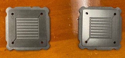
Figure 1: Graphite flow plates
As previously discussed, there are several electrolyte solutions that can be used to achieve the charging and discharging of the fluid in the flow battery. The initial plan was to use the electrolytes consisting of iron(II)/iron(III) sulfate and AQDS [1]. However, when sourcing the AQDS solution the cost of the chemical ($192.37 for 25 g of material [9]) led to a decision to pursue a cheaper alternative. Part of the benefit of a flow battery is its relative simplicity and potential to be a low-cost widely available product. The ferrous chloride electrolyte solution is available for a much lower cost and can be easily sourced from the UP chemistry department.
Results
Due to time constraints, testing for charge and discharge capabilities of the battery were not conducted. Once the battery was constructed, there were problems with getting the fluid to flow correctly through the cells without leaking through the gasket material. Testing was conducted with water that was pumped through the system with 12V DC pumps found in the Shiley 104 lab space (Figure 2). All tests resulted in more water leaking than was desired to test with the electrolyte solutions, so the majority of the testing was directed at troubleshooting leaks in the system.
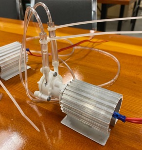
Figure 2: Pumps used for testing
The gasket material was punched with 0.25” holes that lined up with the holes on the graphite flow plates. Originally, 0.125” holes were punched, but the gasket material compressed too much to allow water to flow through. In the first iteration of the battery design, only two holes were punched in the gasket material to allow the fluid to flow across the flow channel and then through the cell to the next plate. However, the gasket restricted fluid flow through the inlet when compressed (Figure 3), so four holes were cut in the gasket, with the Nafion™ membrane directing the appropriate pattern of flow shown in Figure 4.
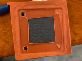
Figure 3: Gasket that restricts flow through battery
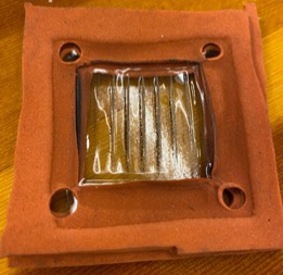
Figure 4: Final gasket assembly with Nafion™ membrane
After making these changes testing was conducted using one 12V DC pump to push the water through one inlet and outlet of the battery. Testing was met with mixed results, as the battery assembly leaked water through the edges of the gasket material but was able to move water from one inlet fitting to the outlet. When attempting to use two 12V DC pumps to move the water through both inlet fittings to the respective outlets as intended when running the electrolyte solution, it was unsuccessful. The leak around the gasket seal increased an no fluid flowed steadily out of the outlets of the battery.
Discussion
While no attempt was made to charge or discharge the battery, a solid foundation was laid for future work on this project. The next immediate steps should be continuing work on creating a seal with the gasket material. More precise cuts and placement of gaskets may help with the leaks. It is also advised that some sort of guiding system be implemented to make sure that the assembly is correctly lined up with all holes so that the fluid does not have trouble flowing through. This may be able to be achieved by 3D printing a housing that will line up all materials with the end plates. Additionally, it may be worth working with the shop to design custom graphite flow plates so that O-rings could be used instead, as they may provide a better seal. Information on machining graphite is easy to find so it may just take trial and error working with Jacob Amos in the University of Portland shop to achieve manufacturing. The Nafion™ membrane was also compressed and deformed when the assembly was clamped together. To avoid having the membrane be affected and deformed by the flow channel, it is recommended to construct a casing for the membrane that will keep it close to the flow channels but not allow it to be compressed into the channels themselves. Once this is completed, testing should be conducted to measure voltage and current produced by the flow battery to measure performance of the electrolyte solutions. While work was unable to be conducted this semester on how concentration of the electrolyte impacts energy storage, this is likely a promising experiment to conduct to see what the optimum electrolyte solution concentration is.
Conclusion
Iron-based flow battery technology is a promising solution for the future of energy storage. The abundance of available iron makes it a much more promising long-term solution than vanadium-based systems, and the scalability and charge cycle duration give it an advantage over Li-ion storage options. Energy storage is essential for future of renewable energy, and flow batteries provide a great opportunity for lasting sustainable energy storage.
Acknowledgements
The author would like to thank Dr. Jordan Farina, Jacob Amos, and the entire University of Portland Shiley School of Engineering for making research on this project possible.
References
[1]. Bo Yang et al 2020 J. Electrochem. Soc. 167 060520
[2]. “Fact Sheet: Energy Storage (2019),” EESI, 22-Feb-2019. [Online]. Available: https://www.eesi.org/papers/view/energy-storage-2019. [Accessed: 05-May-2021].
[3]. “Electricity Storage,” EPA, 03-Apr-2018. [Online]. Available: https://www.epa.gov/energy/electricity-storage. [Accessed: 05-May-2021].
[4]. H. Ibrahim, A. Ilinca, J. Perron, “Energy storage systems—Characteristics and comparisons, Renewable and Sustainable Energy Reviews”, Volume 12, Issue 5,
[5]. Adriano Sciacovelli, Yongliang Li, Haisheng Chen, Yuting Wu, Jihong Wang, Seamus Garvey, Yulong Ding, “Dynamic simulation of Adiabatic Compressed Air Energy Storage (A-CAES) plant with integrated thermal storage – Link between components performance and plant performance”, Applied Energy,Volume 185, Part 1 2017
[6]. Aswin K. Manohar et al 2016 J. Electrochem. Soc. 163 A5118
[7]. Mohammed Al-Yasiri, Jonghyun Park, “A novel cell design of vanadium redox flow batteries for enhancing energy and power performance”, Applied Energy, Volume 222, 2018
[8]. Fuel Cell Store. [Online]. Available: https://www.fuelcellstore.com/. [Accessed: 05-May-2021].
[9]. “ANTHRAQUINONE-2 7-DISULFONIC A,” ANTHRAQUINONE-2 7-DISULFONIC A | Fisher Scientific. [Online]. Available: https://www.fishersci.com/shop/products/anthraquinone-2-7-disulfonic-a/507490435?searchHijack=true&searchTerm=853-67-8&searchType=RAPID&matchedCatNo=853-67-8. [Accessed: 05-May-2021].
University of Portland
5000 N. Willamette Blvd.,
Portland, Oregon 97203-5798
503.943.8000